BACK
PINBALL SIMULATOR GUI
The simulator is a graphical front end for the logic you will flash into your routers.
Its purpose is to educate users on how routes are determined so that routers may be efficiently placed.
Click here to get the Microsoft NET library. (869K bytes)
Click here to get the Pinball Simulator (380K bytes).
SCREENSHOT
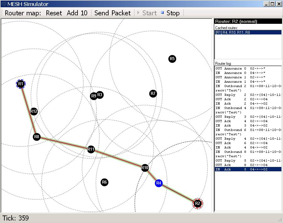
SIMULATOR WINDOWS
The simulator window is divided into three window panes:
1. Router Map, This is where the routers and route path will be displayed.
2. Cached Routes, This displays the previously taken routes from a selected router.
3. Router Log, This displays the traffic from a selected router.
MOUSE OPERATION
Left Click on empty Router Map area, Place a single normal power router on the Router Map.
Left Click on an existing router, Select the router to display Cached Routes and Packet Log.
- The dotted circle indicating the RF range of the router will be highlighted, and all routers within
RF range will be colored blue.
Right Click on a selected router, Drop down an options menu:
- Set Source, Select this router as the source of a test packet.
- Set Destination, Select this router as the destination of a test packet.
- Increase Power, Increase the power of this router by one level. (There are three levels.)
- Decrease Power, Decrease the power of this router by one level.
- Disable, Disable this router's transmitter and receiver.
- Delete, Remove this router from the Router Map.
CONTROLS
The top of the simulator window holds the following controls:
- Reset, Clear the Router Map and all cached routes.
- Add 10, Randomly place 10 normal power routers on the Router Map.
- Send Packet, Send a single packet from the selected Source to the selected Destination router.
- Start, Allows the simulation to be restarted after STOP has been clicked.
- Stop, Stop the simulator so logs and states can be observed.
A SIMPLE TEST RUN
1. Start the simulator (or click Reset).
- The Router Map area will be clear of routers.
2. Left click the mouse on the Router Map area.
- A router will be placed on the Router Map. It will be assigned the number R1.
- (In the actual routers, the MAC address is used to generate a unique router designator.)
3. Move the mouse away from the first router, but still within the dotted RF range, and left click again.
- A second router will be placed on the Router Map and assigned the number R2.
4. Right click on the first router and select Set Source.
- The selected router will be outlined by a blue dotted line indicating it is the source for test packets.
5. Right click on the second router and select Set Destination.
- The selected router will be outlined by a red dotted line indicating it is the destination for test packets.
6. Click on Send Packet.
- A green line overlayed by a red line will be drawn between the two routers
